PRE-PROGRAMMING

ELECTRONICS 101
ELECTRICAL SIGNALS
Before we start telling it what to do, it's important to understand how the machine works.
How do we send and receive information?

Information exchange
Communication and information exchange as we know it, is only possible due to the work and studies of several scholars and physicists across the centuries.
electromagnetism
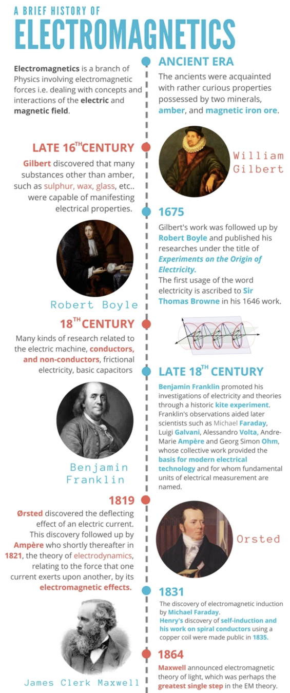
These studies were eventually unified into what we know today as the Electromagnetism Theory.
The Electromagnetic Theory is complex and involves a series of concepts and mathematical equations, but simply put, it states that:
electromagnetism
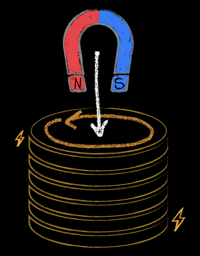
1) A change in magnetic flux over time can induce an electric field and, therefore, an electric current
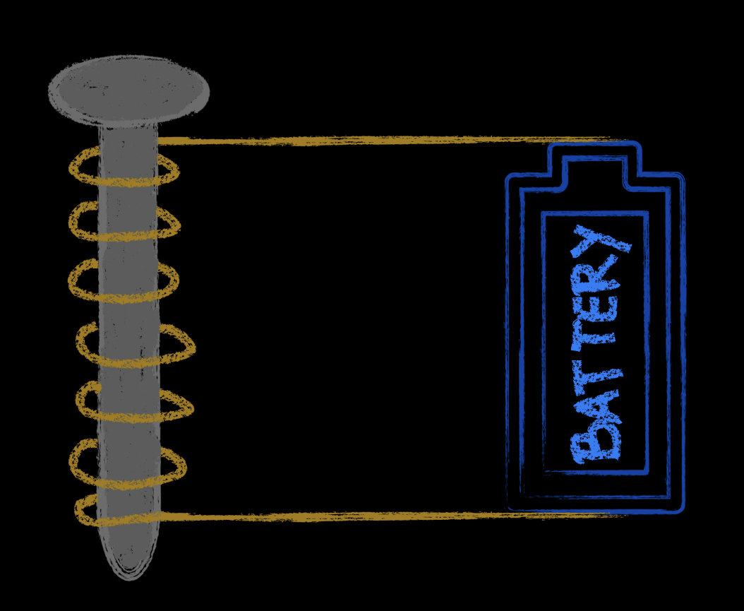
2) An electric current can generate a magnetic field
Sound waves produce a vibration in the microphone's diaphragm, making it move back and forth.
The wire's movement over the magnetic field created by the magnet creates an electric current -
ELECTRICAL SIGNAL.
A PRaCtical case

Conceptually speaking, a signal is an electromagnetic representation of the data we want to transmit from one system (or network) to another.
Signals can be analog or digital.
ELECTRICAL SIGNALS

A time-varying signal that continually represents the change in values of some variable.
An analog signal, in a defined period, can represent an infinite number of values.
Analog signal

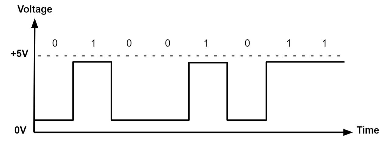
A digital signal represents data as a sequence of discrete values. The possible values are finite.
Digital signals are used in all digital electronics.
Digital signal
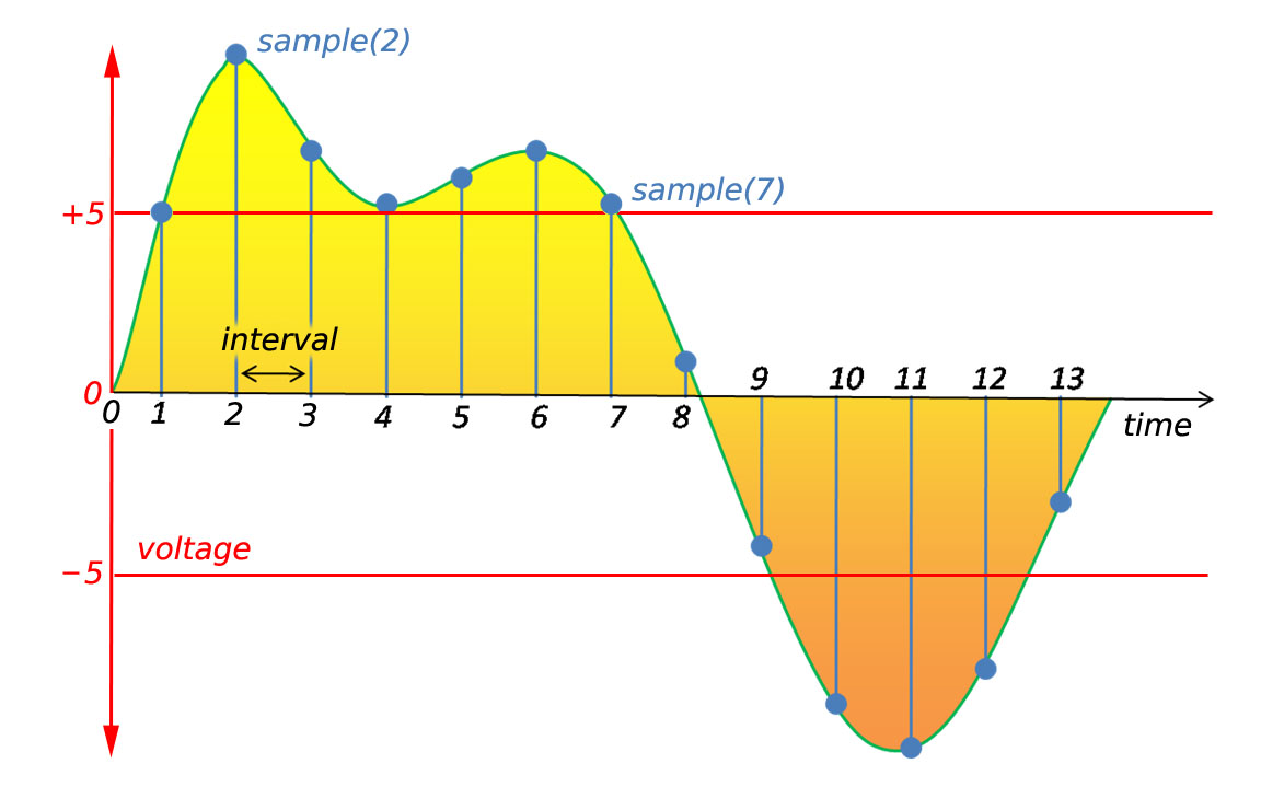
Process by which analog signals are converted into digital signals.
Samples are taken at intervals, that can be wider or narrower.
Digital Sampling
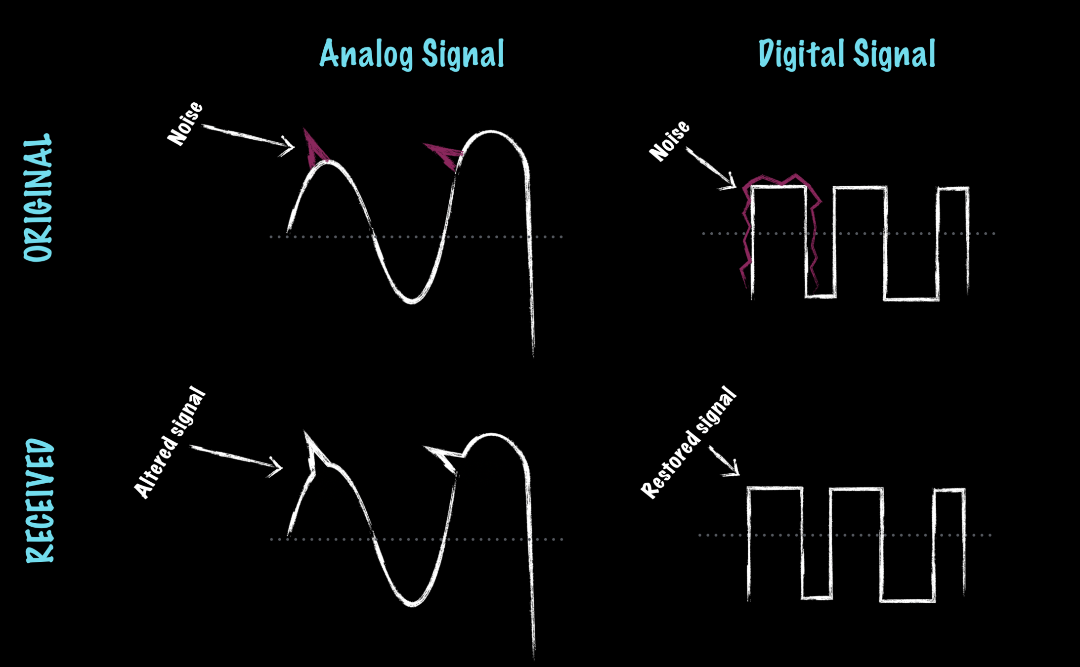
Analog signals are more susceptible to noise.
We will mostly focus on digital signals, because that's how computers work.
Digital vs. Analog
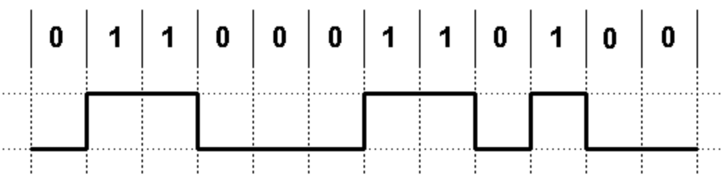
In most digital circuits, the signal can have two distinguishable levels:
- 0 - representing a residual voltage value (zero volts)
- 1 - representing the maximum voltage supply
But why 0's and 1's? What kind of system is this?
BINARY SIGNAL
BINARY NUMERAL SYSTEM
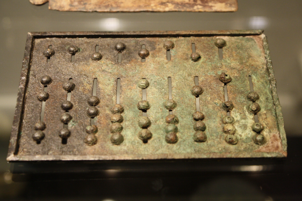
The necessity to represent quantity has been present in human life since prehistoric times.
A Little History...


During the evolution of numeral systems, one invention was of particular importance for the way we deal with numbers today: the invention of a symbol to represent zero!
This invention revolutionized the way we looked at numbers and counting, introducing the first positional numeral systems.
THe importance of nothing
But what is a numeral system, after all?
A numeral system is a mathematical notation for representing numbers.
There are several all over the world, but the modern civilizations mostly use the Arabic Numeral System.
Numeral Systems
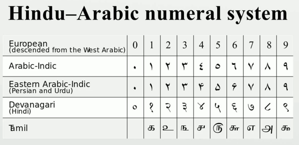
The Arabic Numeral System is what we call a base 10 system.
Decimal system
What is the base?
The base represents the amount of different symbols used to represent quantity.
Why 10?

There are a couple of rules you need to know in order to work with ANY positional numeral system:
- Exhaust all available symbols in order
- Start over from 1, but before you can move on the the next symbol, combine it with all the available symbols in order.
How do positional numeral systems work?

So, what does the number 367 mean?
decomposing numbers

Computers know only two states: off and on.
These two states can be represented by 0 and 1, respectively.
Binary numeral system
0
1
The Binary Numeral System is a base 2 numeral system.
Let's count:
10
11
100
101
1000
1001
110
111
Binary to decimal conversion

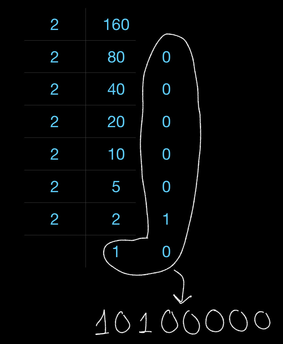
decimal to binary conversion
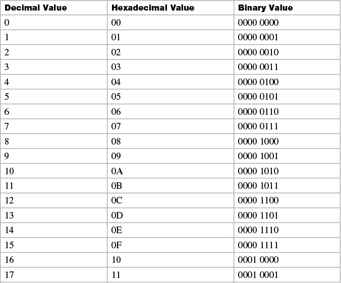
HEXADECIMAL
A base 16 numeral system, invented as a human friendly way of reading binary numbers.
NEXT
We went through the basics of how information gets translated into something a computer can understand, so we can work with it, send it or receive it.
By modulating electrical signals, we can transmit everything from audio, text, images, video, etc.
But how can we modulate the electric current inside a computer?
TRANSISTORS
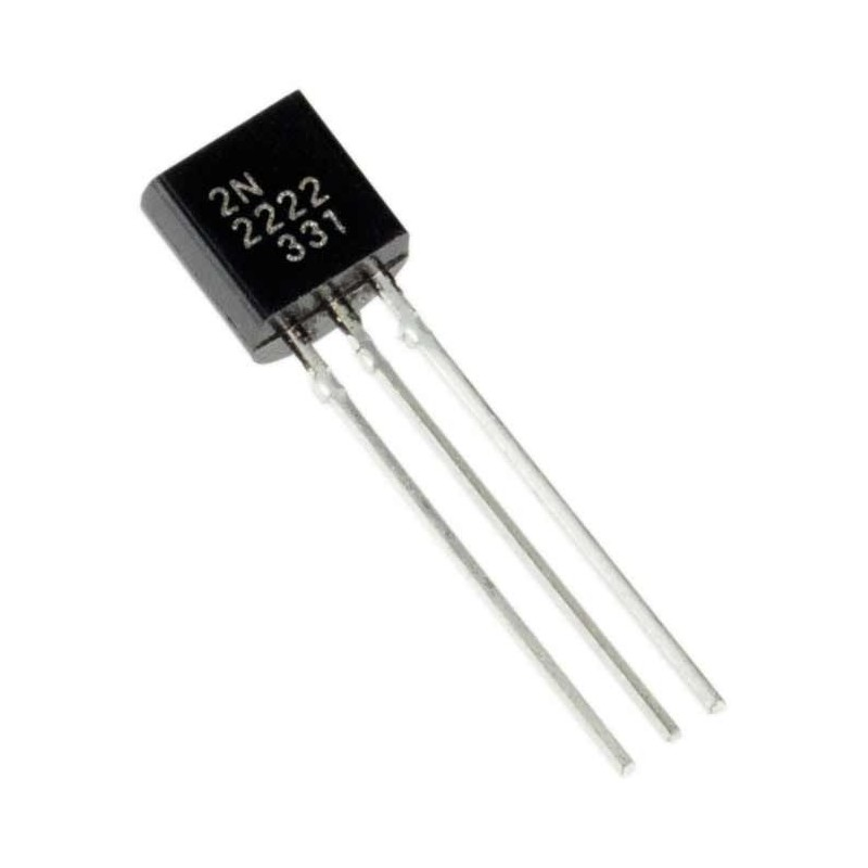
What is a transistor?
Semi-conductor devices made of silicon that regulate current flow.
Invented at Bell Labs.
Used to amplify analog signals or switch digital signals.
The key component in practically all modern electronic devices, with the latest maximum count passing the trillion mark.
DOPING

Doping is the process of introducing impurities into a semiconductor material for the purpose of changing its electrical properties.
Silicon is a semiconductor; to conduct and amplify electrical signals, atoms of boron, phosphorus, or arsenic are used to dope it.
There are two types of doping: N (excess electrons) and P (lack of electrons).

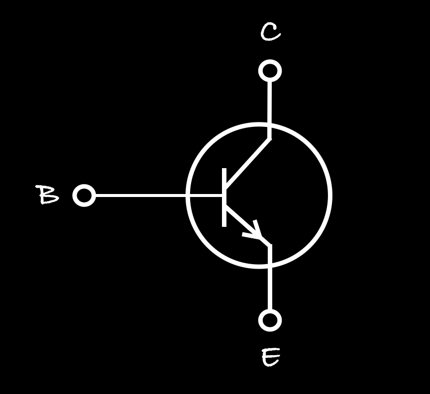
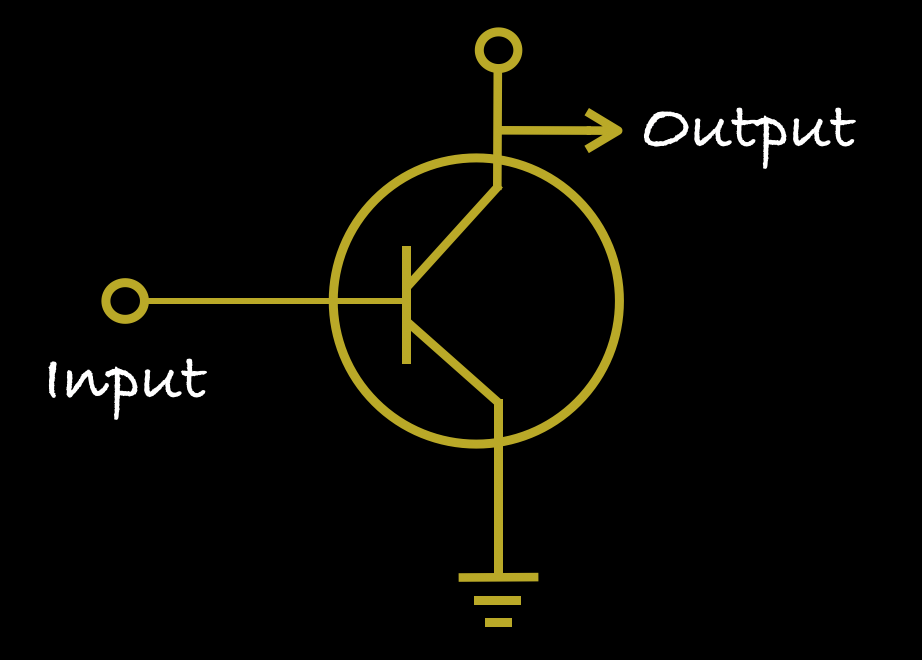
How does a transistor work?
A transistor is composed of three different parts:
COLLECTOR - negatively doped
BASE - positively doped
EMITTER - negatively doped
Current on the base controls the emitter current.
The water analogy
A small current on the base modulates a large current on the emitter.
INTEGRATED CIRCUITS
An integrated circuit is an assembly of small electronic devices (transistors, diodes, etc.). It can be as small as a few square millimeters.
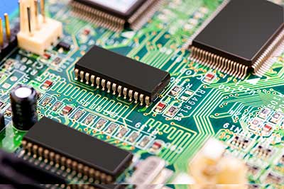
Integrated circuits on a PCB.
NEXT
We can put a few transistor switches together to make something called a logic gate, which compares several input currents and gives a different output as a result.
Logic gates let computers make decisions using a mathematical technique called Boolean Algebra.
BOOLEAN ALGEBRA
A Little History
In Ancient Greece, Aristotle devised a system of logic based on only two types of propositions: true and false. This system led to the foundational rules of logic.
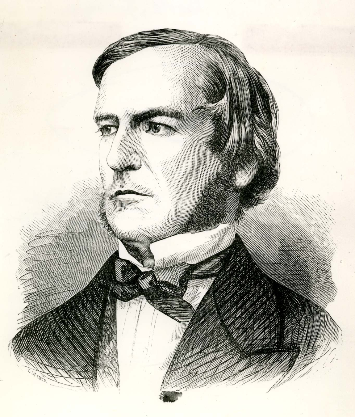

Centuries later (1800's), the mathematician George Boole worked to give symbolic form to Aristotle's logic system, hence creating what we now know as Boolean algebra.
Algebra
Rules of Boolean algebra differ from the rules of regular algebra.
| REGULAR ALBEBRA | BOOLEAN ALGEBRA |
|---|---|
| Finds the numerical value of a statement | Determines the truth of a statement |
| Multiplication, division, addition, subtraction | Conjunction, disjunction, negation |
Boolean Algebra
Boolean algebra is a branch of mathematics that deals with operations on logical values with binary variables.
Boolean variables are represented as binary numbers representing truth: 1 or 0 (true or false).
Boolean algebra is part of virtually every programming language that exists.
The Laws of boolean algebra
Annulment Law – A term AND'ed with a “0” equals 0 or OR'ed with a “1” will equals 1
Identity Law – A term OR'ed with a “0” or AND'ed with a “1” will always equal that term
Idempotent Law – An input that is AND'ed or OR'ed with itself is equal to that input
The Laws of boolean algebra
Commutative Law – The order of application of two separate terms is not important
Double Negation Law – A term that is inverted twice is equal to the original term
Complement Law – A term AND'ed with its complement equals “0” and a term OR'ed with its complement equals “1”
de Morgan's theorem
The mathematician Augustus de Morgan defined two rules:
- Two separate terms NOR'ed together is the same as the two terms inverted and AND'ed. Example: (A+B)' = A' . B'
- Two separate terms NAND'ed together is the same as the two terms inverted and OR'ed. Example: (A.B)' = A' + B'
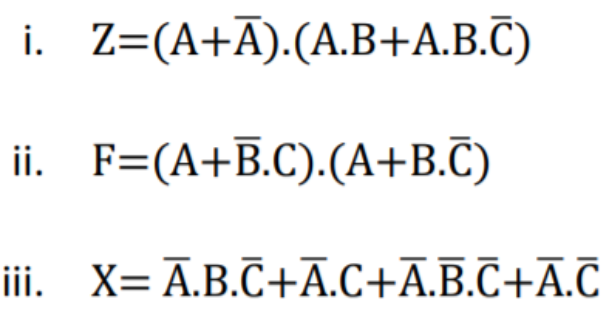
EXERCISE
NEXT
With the help of Boolean logic, we can use transistor switches to create logic gates.
But what exactly are logic gates?
LOGIC GATES
What are logic gates?
Logic gates are the building block of any digital system.
A logic gate is basically an electronic circuit with one or more inputs and one output.
The relationship between the inputs and output is based on
Boolean logic.

LOGIC GATE
What are logic gates?
Logic gates are built with transistors.
With a single transistor, we have one input and one output.
If the input (base) is on, then there's output on the emitter. If not, there isn't.
Playing with transistors, we can create the three basic logic gates: NOT gate, AND gate, and OR gate.
TRUTH TABLES
Before we get into the specifications of each logic gate, there's one more concept we need to grasp: truth tables.
A truth table is a mathematical table used in logic to set out the results of logical expressions.
| INPUT | OUTPUT |
|---|---|
| TRUE | TRUE |
| FALSE | FALSE |
Truth table showing the operations on a transistor.
It doesn't look very exciting, does it?
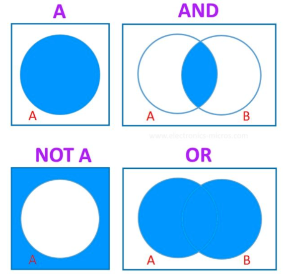
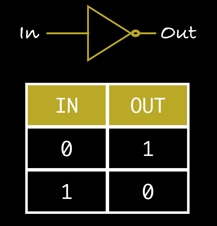
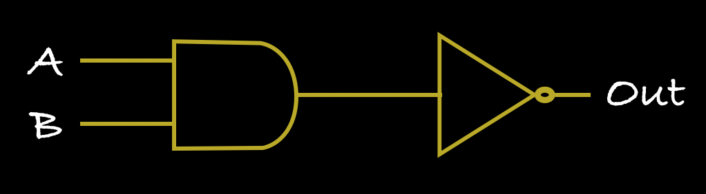
NOT GATE
The NOT operation takes a single boolean value and negates it.
We can create it by taking the output wire from the transistor's end and attaching it before the input wire.
NOT GATE
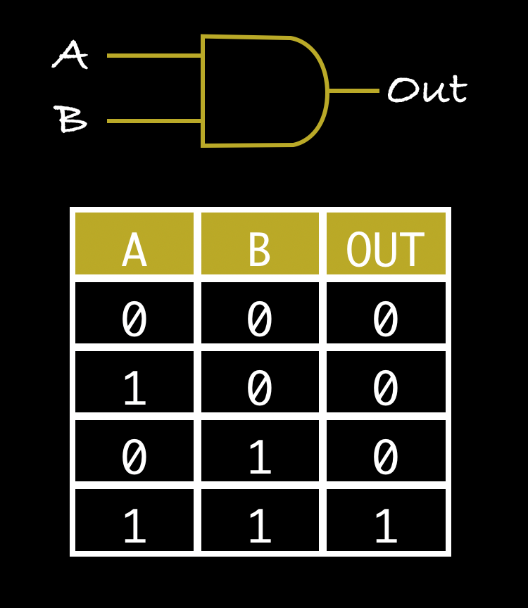
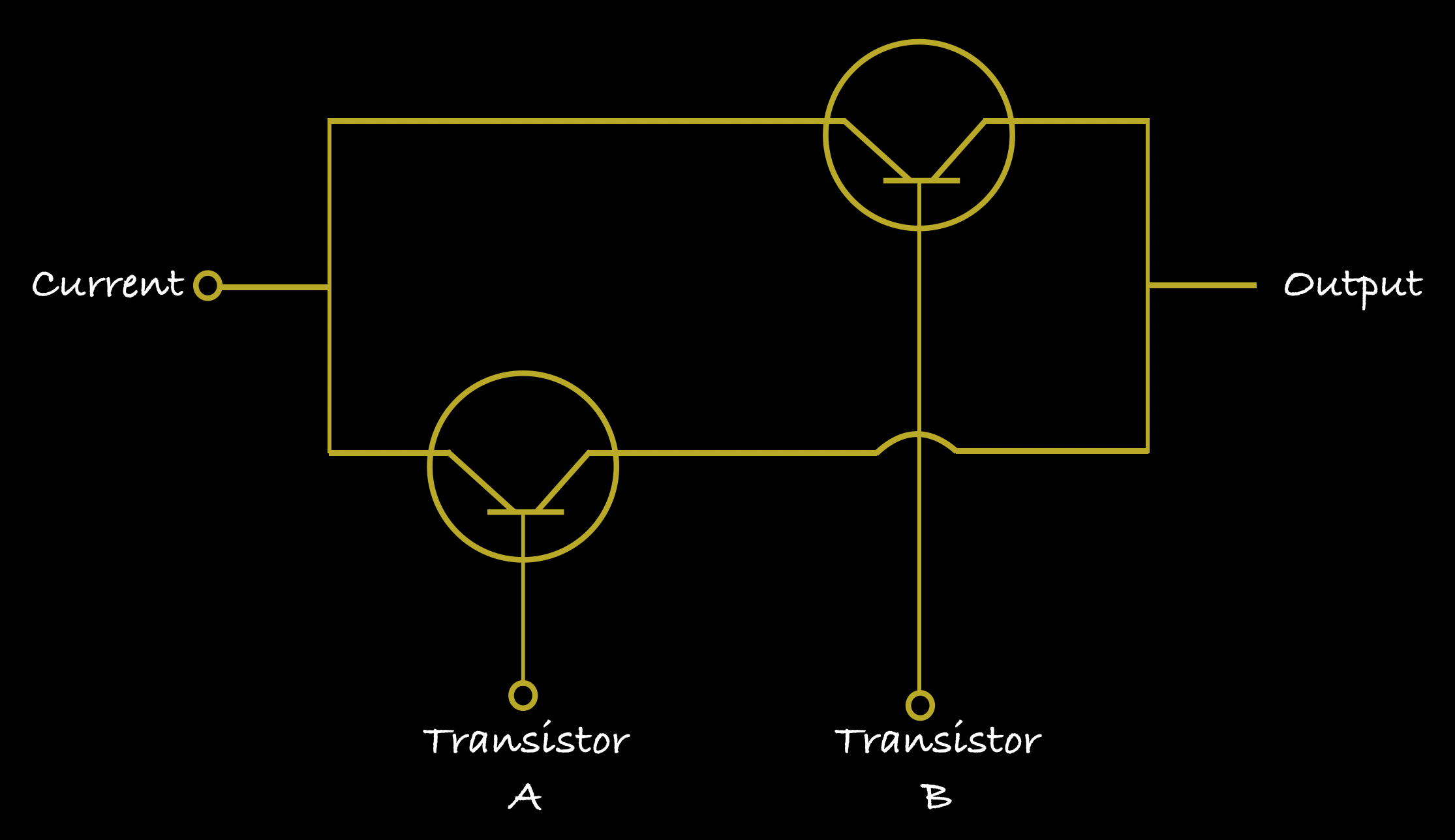
AND GATE
The AND operation takes two inputs and produces a single output.
We can create it by joining two transistors in series.
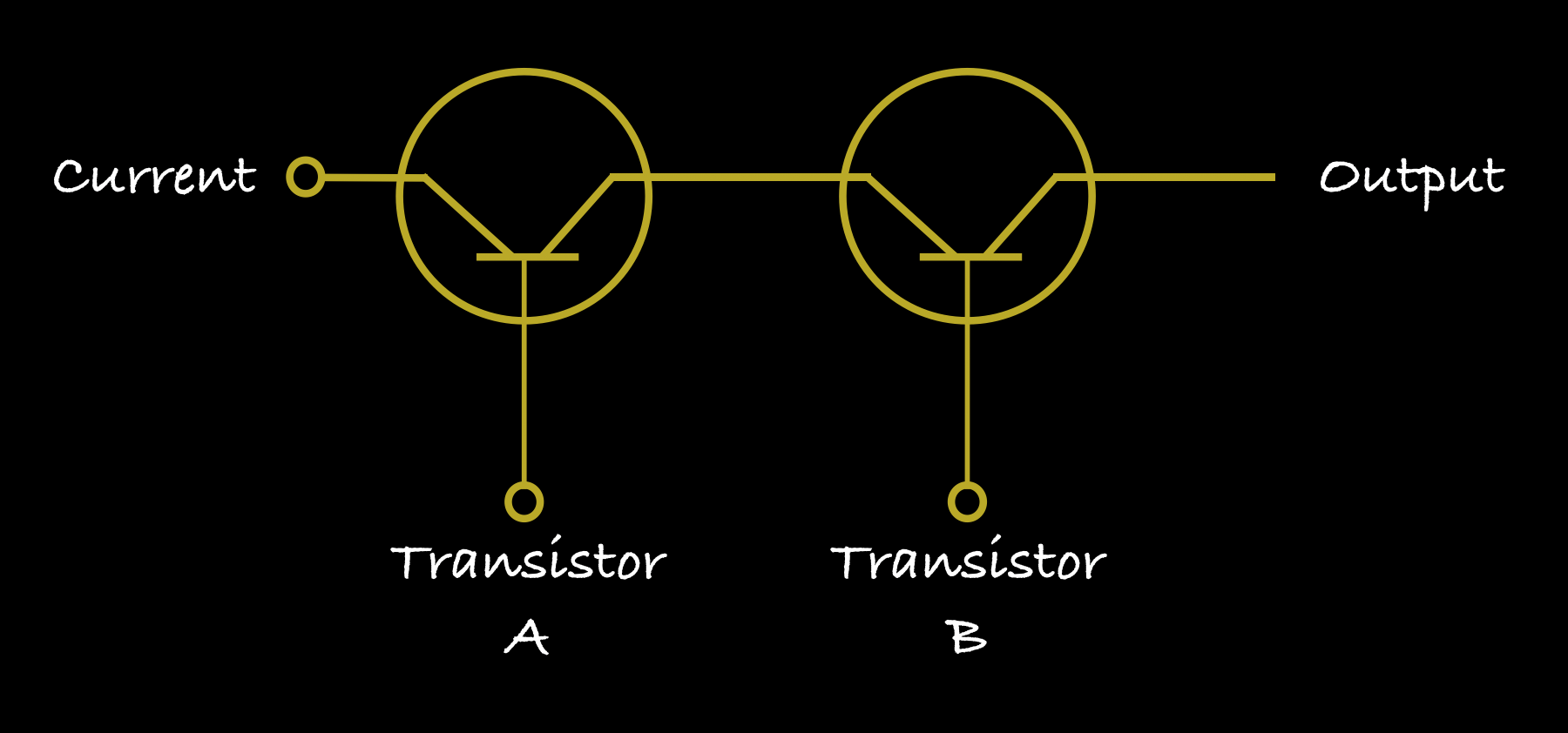
AND GATE
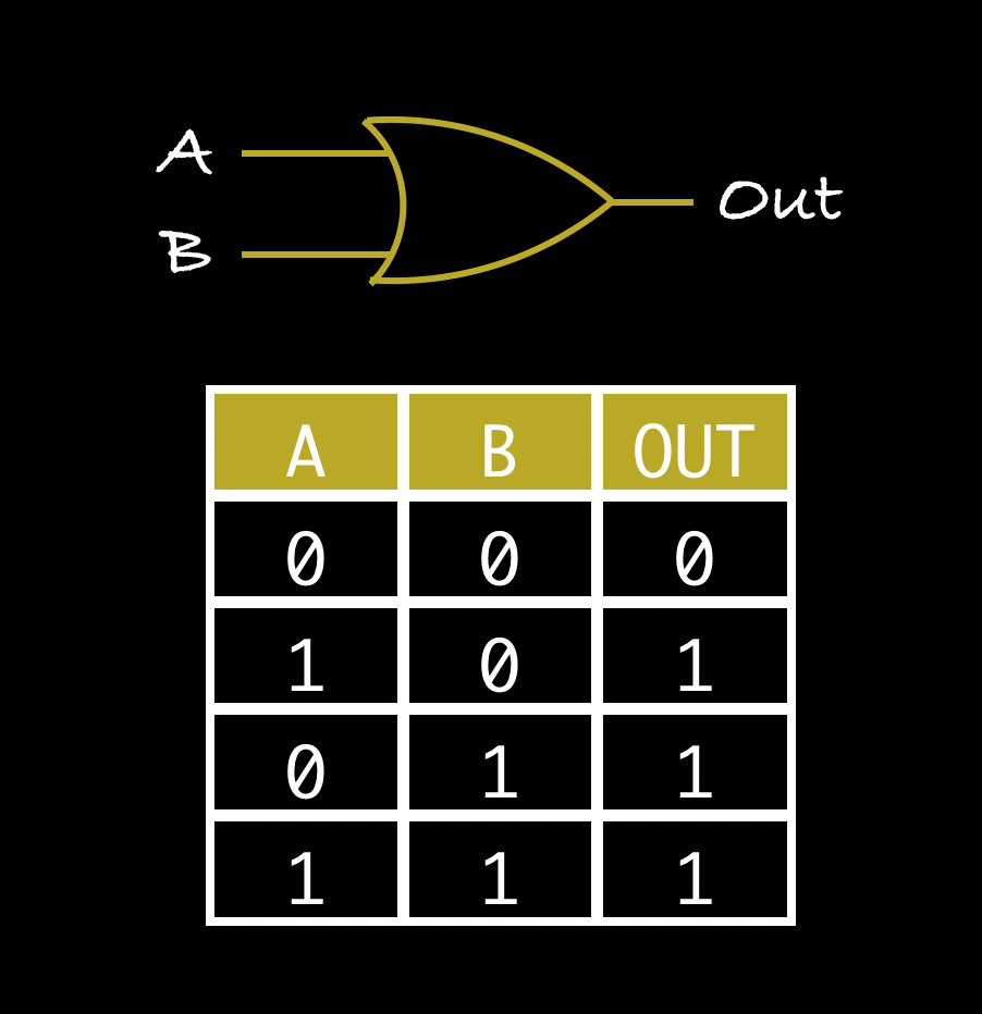
OR GATE
The OR operation takes two inputs and produces an output.
Once again we can connect two transistors, but this time in parallel.
OR GATE
COMPLEX GATES
Putting together a few basic logic gates, we can create more complex circuits. These include:
- XOR gate
- NOR gate
- XNOR gate
- NAND gate
Let's take a look at the XOR and NAND gates.
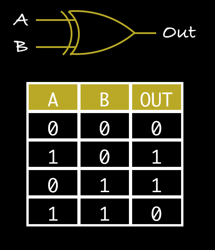
XOR gate
XOR stands for Exclusive OR.
This one works very similarly to an OR gate, except when both inputs are true.
XOR gate
NAND gate
NAND stands for Not AND.
This gate basically negates the result of the AND operation.
NAND gate
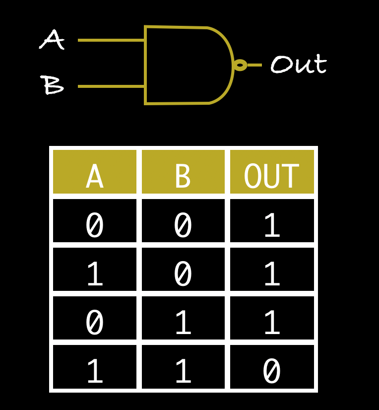
NAND gate
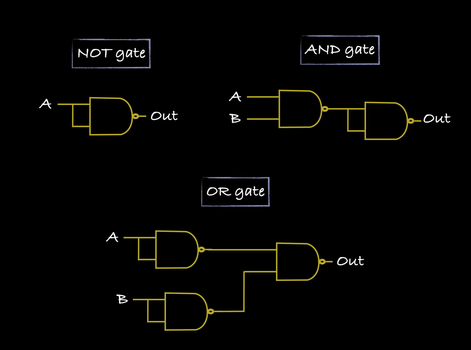
FUN FACT: Using NAND gates, we can create any other logic gate.
EXERCISE
Represent the following functions using logic gates:
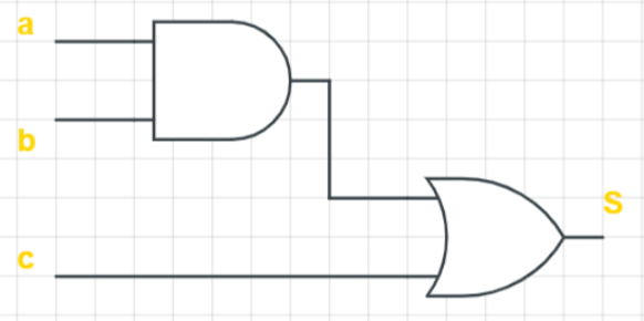
a) Y = (A.B) + C
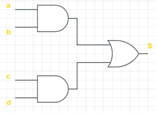
b) Y = (A.B) + (C.D)
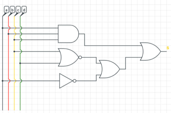
c) Y = (A.B.C) + [ (C + D)' + A']
solution
Y=(A.B) + C
solution
Y=(A.B) + (C.D)
solution
Y=(A.B.C) + [(C + D)' + A']
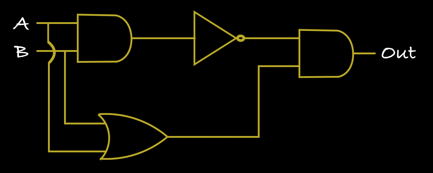
EXERCISE
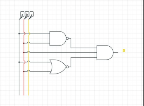
Determine the functions corresponding to the following logic circuits:
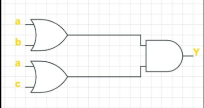
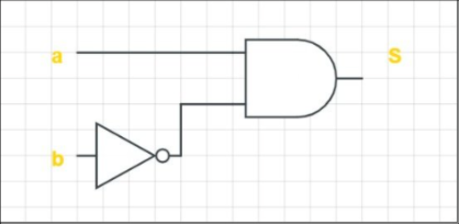
Solution
a) S = A.B'
a) Y = (A.B) + (A.C)
a) S = (A.B)' + (A+B)'C
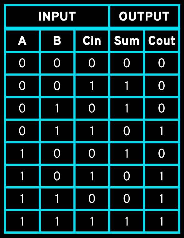
EXERCISE
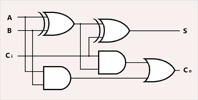
| A | B | Cin | Sum | Cout |
|---|---|---|---|---|
| INPUT | OUTPUT |
|---|
solution
Electronics 101
By Soraia Veríssimo


